Interpreting Means-Plus-Function Claims – A Real World Example
by admin - November 12th, 2017. Filed under: IP Management, Patent Claim Construction, Patents.In my last post, I discussed how courts construe “means plus function” clauses in a patent claim. I also discussed the danger for patent owners when they rely upon means plus function clauses if there is no corresponding structure and/or no clear link to the structure in the patent specification.
Recall that “means-plus-function” clauses are governed by a patent statute which is now codified at 35 U.S.C. §112(f). Although this provision has been in the statute since 1952, the way that courts have interpreted the provision has radically changed over the years. In fact, twenty to thirty years ago, means-plus-function clauses were extremely popular and often used by patent lawyers. However, as courts have imposed a greater number of restrictions in recent years on this type of claims (especially since the late 1990s), the popularity of the means-plus-function clause has substantially declined. In 2013, Dennis Crouch, a famous and reputable law professor (among patent lawyers), charted the decline of the means plus function clauses for the years 2001 to 2013. His chart can be found here.
This and related posts will explore the process generally used by courts and patent attorneys to analyze means-plus-function clauses. To illustrate the process, I have selected US Patent Number 6,289,319 issued to Lockwood because this particular patent contains several interesting and varied means-plus-function clauses. (By way of background, the US 6,289,319 Patent is purportedly to be exclusively licensed to Landmark Technologies).
Note: This description of the process for analyzing the US 6,289,319 patent represents the author’s personal opinion. This posting is not meant to convey legal advice and no one should rely on this post in any manner whatsoever. If you have actual questions about the validity or scope of the US 6,289,319 patent, please consult with your own patent attorney.
The US 6,289,319 Patent contains a single independent claim. The claim presumably covers an automatic data processing system which includes: (1) a central processor, (2) a terminal, and (3) a means for linking the terminal to the central processor. For simplicity, I will start analyzing the central processor.
The central processor of the US 6,289,319 Patent is exclusively defined by means-plus-function clauses. The claim provisions relating to the central processor are reproduced below:
a central processor programmed and connected to process a variety of inquiries and orders transmitted from said remote sites; said central processor including:
means for receiving information about said transactions from said remote sites;
means for retrievably storing said information;
means responsive to data received from one of said terminals for immediately transmitting selected stored information to said terminal; and
means responsive to an order received from a terminal for updating data in said means for storing;
First I should point out that under a few relatively recent Federal Circuit cases, the “central processor” clause might be considered a means plus function clause. But, that is a discussion for another post. For this post, I will focus on the first of the four traditional means-plus-function clauses that are included in the claimed central processor.
Means for receiving information about said transactions from said remote sites
As discussed in my previous post, the first step is to determine the function of the means-plus-function clause to be analyzed. The function of each clause is determined by a convention claim analysis discussed in a previous post. (In other words, one first looks to the plain and ordinary meaning of the claims, then reviews the specification, reviews the prosecution history, then if absolutely necessary, consults with extrinsic sources.) For purposes of simplicity and this post, however, I will just use claim wording. Thus, the function of the first means-plus-function clause appears to be:
receiving information about said transactions from said remote sites
As explained in previous posts, once I determine the function of the clause under review, the next step is to determine what structure, if any, is disclosed in the specification. In other words, I now need to find some structure which is part of the Central Processor that can perform the function of “receiving information about said transactions from said remote sites.”
Although the specification must show a clear link or association between a structure in the specification and the function, the Federal Circuit has also held that one must not ignore the drawings because the drawings could also reveal a structure associated with the function.
So, I will first review the drawings relating to the central processor. Fortunately, for this post, the only drawing that describes the central processor in the US 6,289,319 Patent is Fig. 1. Fig. 1 is reproduced below. For convenience and only for purposes of this post, I have highlighted several “lines” of Fig. 1 in various colors. The lines are not labeled. So, for purposes of this post, I will assume they must be some form of communication links.
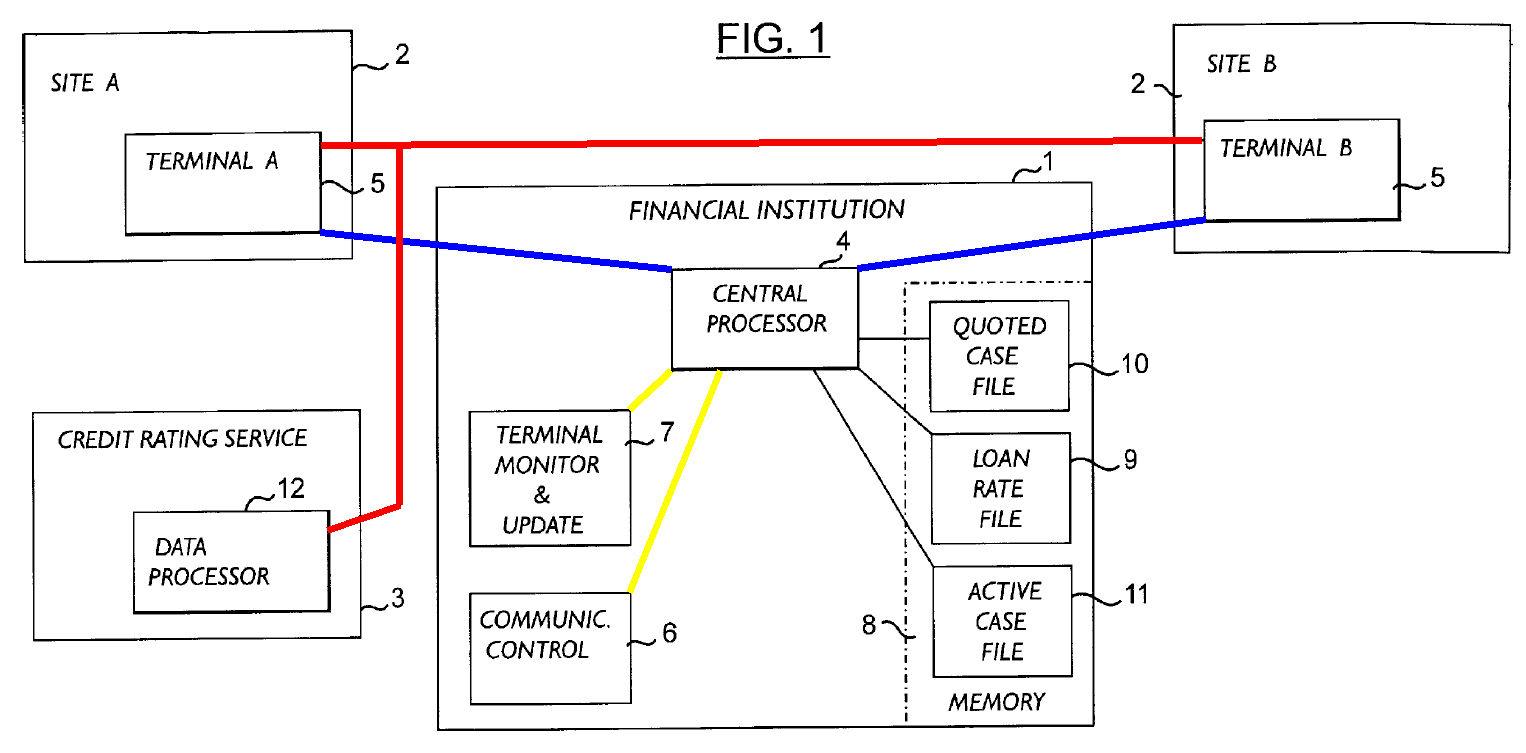
In Fig. 1, the central processor is only represented as a box labeled with a reference numeral “4”. The blue lines appear to establish some form of communication between the Central Processor 4 and the Terminals 5. If the blue lines are communication links, then they simply represent the function of a communication link. Consequently, the blue lines cannot be considered a structure. The red lines are apparently represent some form of communication between the Terminals 5 and the Data Processor 12 of the credit rating service. The yellow lines appear to be some form of internal communication link or path. However, again, these lines are not labeled nor discussed.
As illustrated in Fig. 1, there is a box labeled “Communic Control 6” and another box labeled “Terminal Monitor and Update 7.” As discussed above, the blue lines from the Terminals 5 do directly to the Central Processor and appear to bypass both the Communication Control 6 and the Terminal Monitor and Update 7. So, if the Communication Control 6 or the Terminal Monitor and Update 7 perform the function of “receiving information. . . from said remote sites,” it is not clear from the drawings how this how this function can be performed because there are no links from the Terminals 5 to either of these boxes. In fact, it appears that Communication Control 6 and the Terminal Monitor and Update 7 only communicate with the Central Processor 4.
Furthermore, even if there was a communication link between the Terminals 5 and the Terminal Monitor & Update 7, there is no structure associated with the Terminal Monitor & Update 7 – except a box. The Terminal Monitor & Update 7 is simply defined by the function it performs. Consequently, at least from the perspective of the drawings, the Terminal Monitor & Update 7 cannot provide structure for any function. Although drawn as a box, it is actually described in functional terms. The same holds true of the Communication Control 8.
In summary, there does not appear to be any identifiable structure in Fig. 1 that is included in the Central Processor 4 and is linked or associated with the function of “receiving information about said transactions from said remote sites.”
So, the next step is to search the specification. Because this post is already lengthy, I will search the specification for the corresponding structure in my next post. If you have any questions on this post, however, feel free to contact Bill Naifeh at www.naifeh.com.